Front
Suspension Cutouts
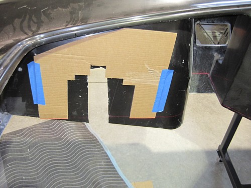
Figuring out where to
make the cutouts for the front suspension is rather tricky. I first
made a cutout that went around the suspension. The idea is to make the
initial cuts close during the initial fit and then open them up later once
the final body position is determined. I used my laser level to level
across from the top of the frame rail just left of the header then across
the bottom of the cardboard, I then trimmed the bottom edge to match
the level line. In order to make these markings transferable to the
body, make sure you level the frame first before completing this step.
After first leveling
the bottom floor pan of the body, I then transferred the level over to the
body and leveled across the attach point and the wheel wheel. After
aligning the cut out along the bottom line, I taped it in place. At
this point, the cut out is positioned properly in the vertical plane but not
horizontally. I scribed the bottom of the cut out form before moving
to the next step.
In order to get things
positioned horizontally, I first used my laser level to confirm that the
hubs are aligned with the center of the shock towers. They are.
I then set up the laser level to shoot between the cutouts for the shock
towers and used a tape measure to center the laser line in each wheel well.
That gave me the center of the shock tower. I then adjusted the
cardboard cutout left or right to align with the laser.
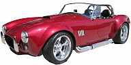
Emergency Brake Cutout
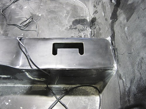
To get the body to set
down on the frame, it is necessary to cut out an area for the emergency
brake handle. To locate this accurately, I removed the handle, sat the
body down on the frame, and drilled the mounting holes up through the
fiberglass. I then used my Dremel to cut the opening to its final
shape.
Wheel Alignment
Before trying to align
the body to the frame, you are supposed to use the frame as a guide.
Well, I did that, but I also found that having the wheel in alignment goes a
long way to getting the look correct.
I don't have any
pictures of this process but I'll try and describe what I did. First
step was to align the rear end so that the rear axle is perpendicular to the
centerline of the frame. Using some frame reference points, I adjusted
the 4-links to accomplish this. Note that the center of the wheel
wells on the body is 10 inches behind the center mounting pad so that's what
I used to align the rear end front-to-back. Next, I roughly centered
the rear end side-to-side using the rotors and a reference point on the
frame.
Then using the rear
wheels as a reference point, I used my laser level to shoot lines forward.
These lines were used to align the front wheels. I used a level to
simultaneously set the toe and the alignment. It took three or four
adjustments until I got the front wheels pointed in the same direction as
the rear, and the toe to be zero.
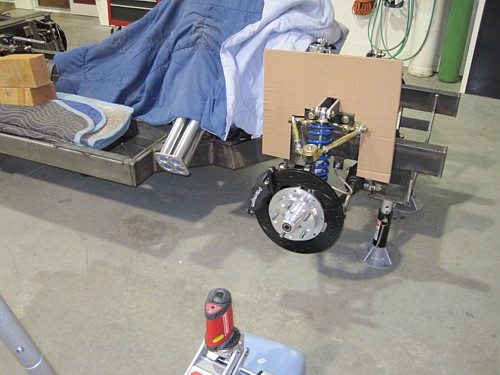
One final step before
setting the body on is to adjust the shocks so they are approximately set to
the same ride height. The best way I could find to do that was to set
the bottom sleeve that is used to tighten the spring down to the same
distance on each shock. The looser the shock spring, the lower the
body will ride down on frame. Once the body is set, I can fine tune
the ride height by adjusting the shocks to ride higher.
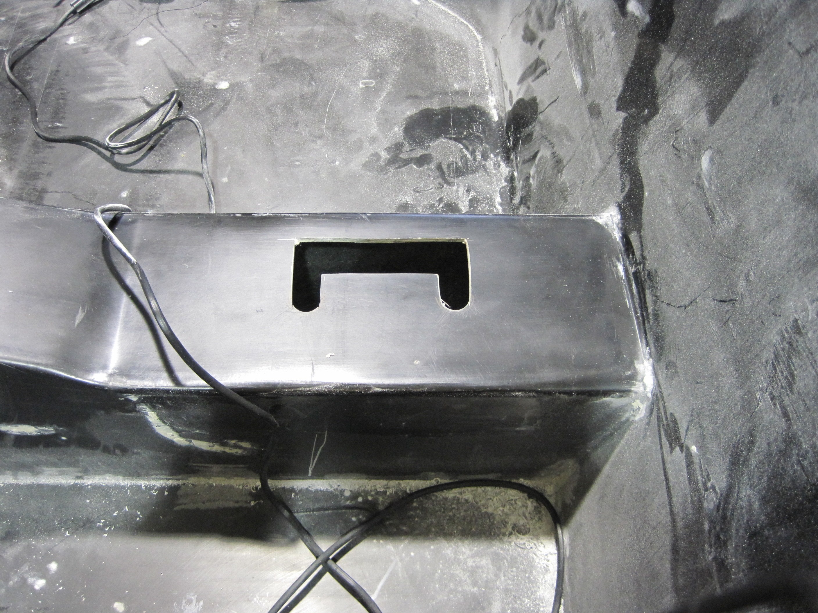
Body to Frame

With the wheels
aligned, I dropped the body down on the frame. The overall alignment
of the body with the frame is pretty good. I have about the same
distance above the tires to the body on all four corners, about 2 1/2
inches. I also checked the center of the wheel wells with the center
of the tires and the rear is perfect. The front ones are off
side-to-side by about 1/2 inch. This is not something I am going to
worry about right now. Later I can adjust the spacers on the lower
control arm to move one wheel forward.
Looking down the car,
I have decent alignment. I'd like to shift the front of the body over
to the right just a tad so I'll have to look at what needs to be ground to
allow that to happen. I didn't worry too much about the rear
alignment. I just tried to get the body centered on the frame.
My adjusting the pan hard bar, the rear end can be moved side-to-side to get
perfect alignment with the rear flairs.
By the way, my rims
use the standard backspacing recommended by Brian for the 17" rims.
The specs can be found on my
Build Specification.
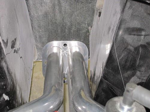
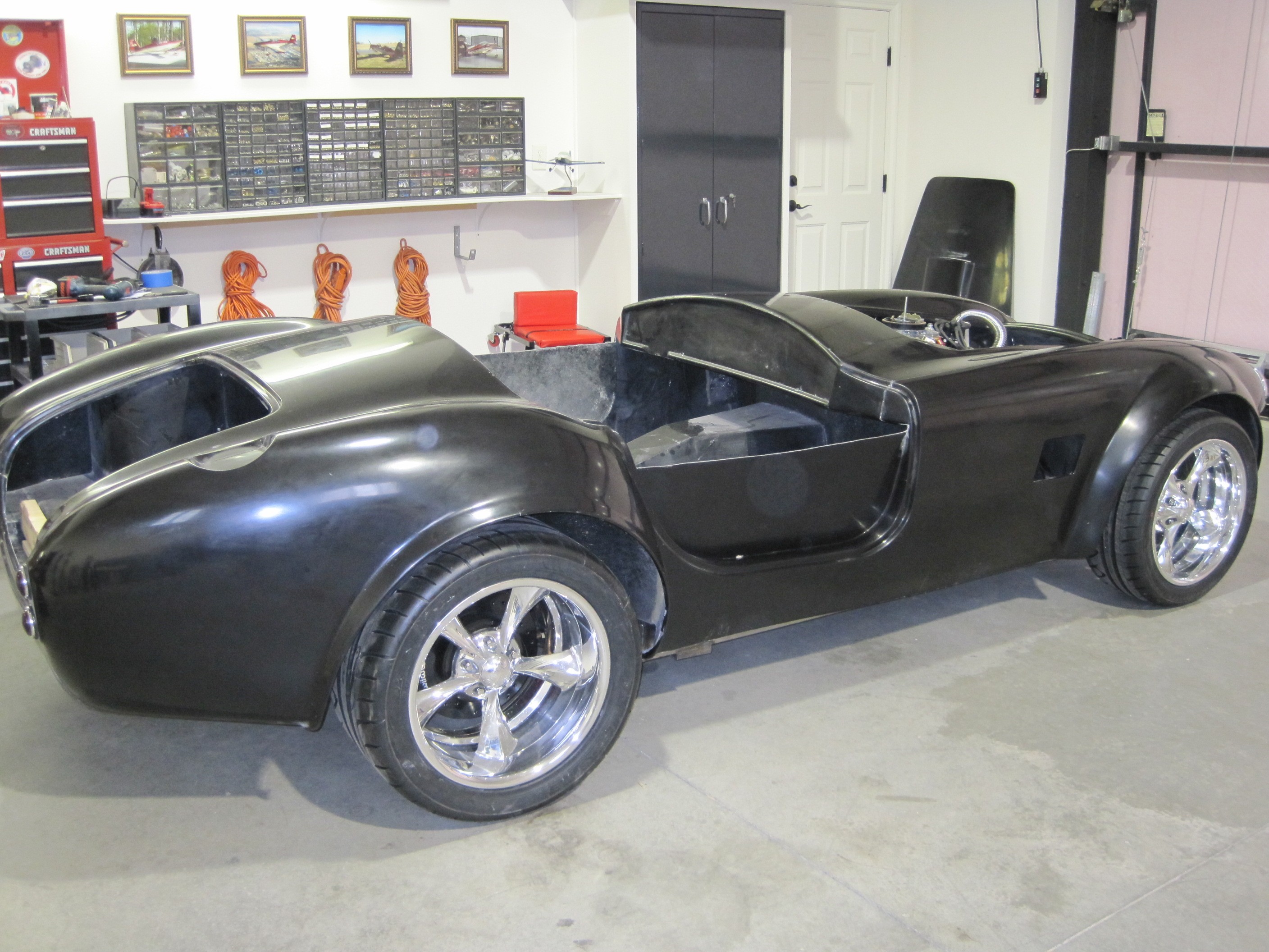
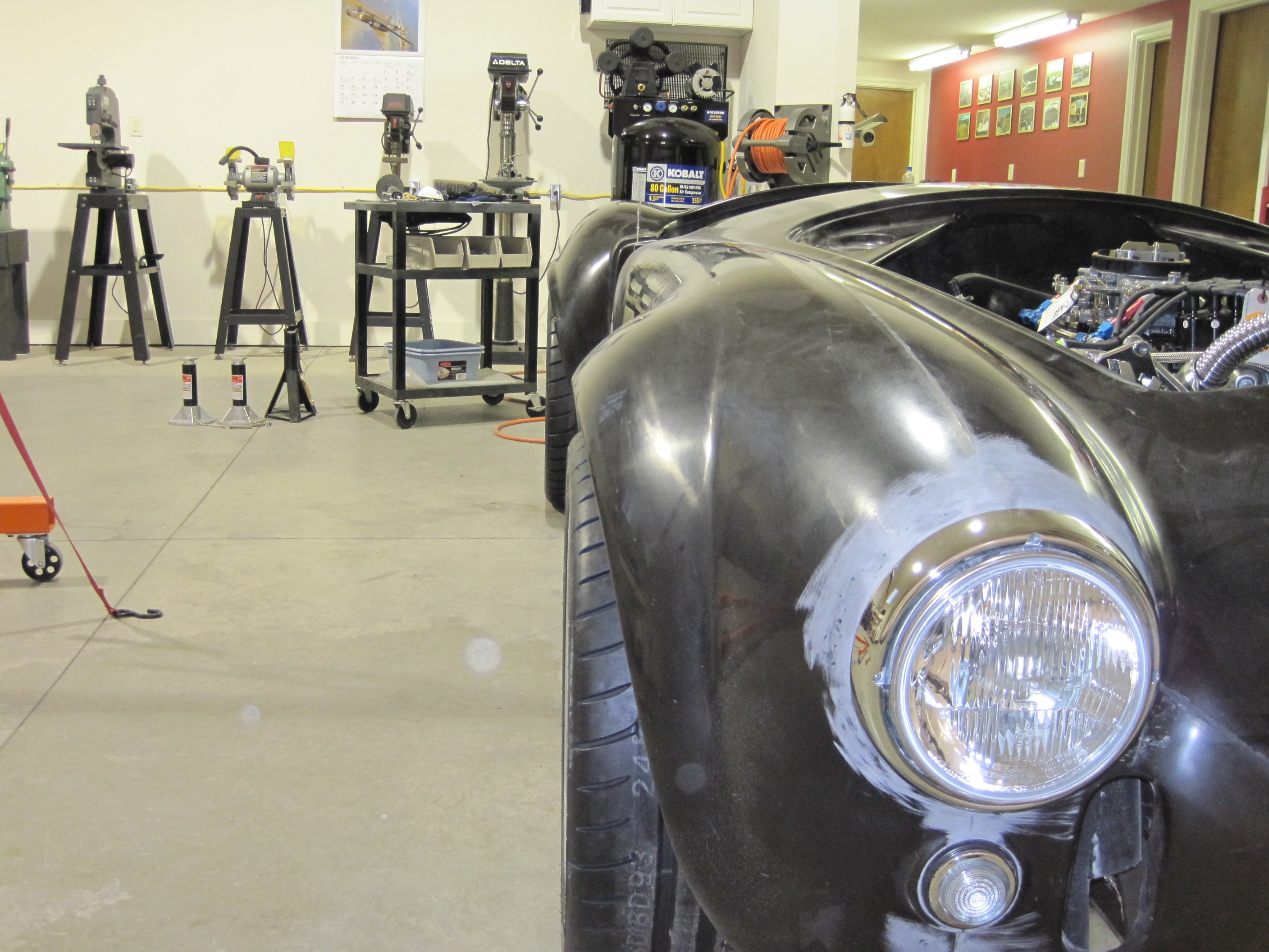
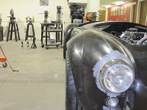
Here is the space I
have on the right side. Just perfect. All that work to move the
engine back 1 inch paid off.

There's plenty of room
on the right side.
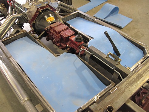
There is a slight
space between the bottom of the floor pans and the trays in the frame.
To fill this space, I used some sleeping bag pads and cut them to shape.
They are made of soft foam, they compress, and they are waterproof.
They are perfect for this application and they will help deaden the sound as
well.
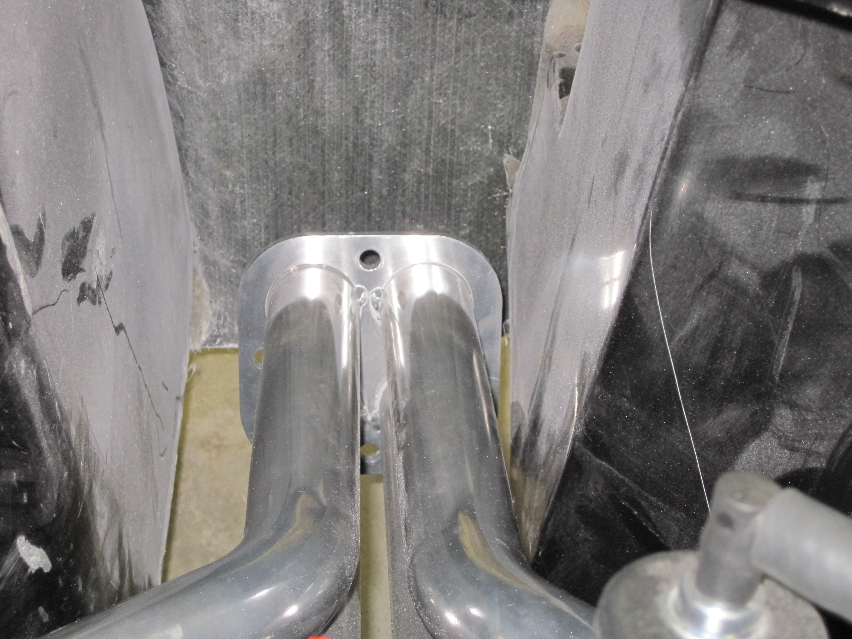
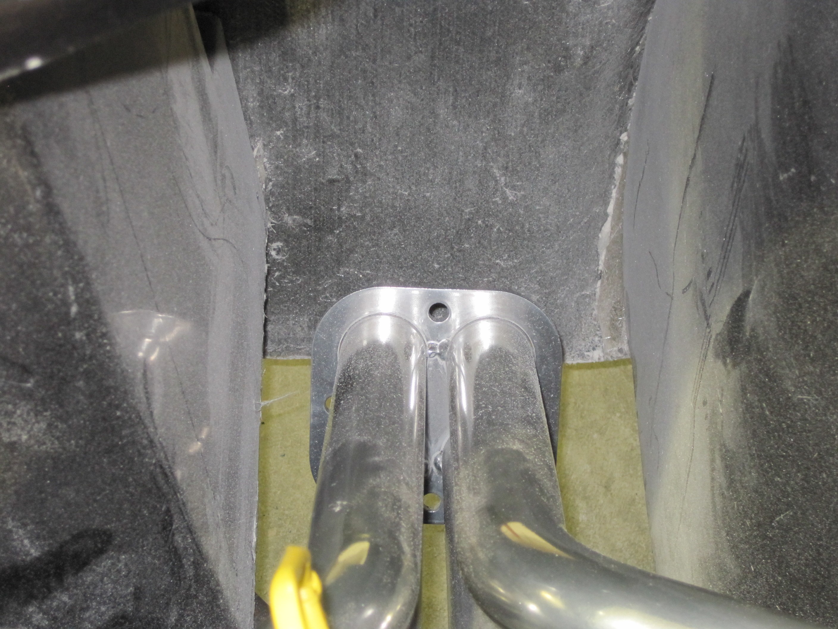
Cockpit Mounts
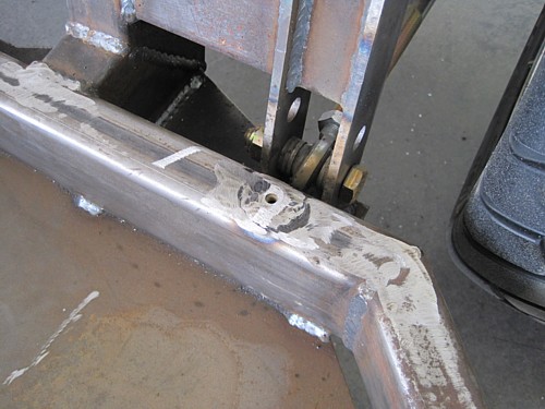
With the position of
the body on the frame finalized, I drilled mounting holes behind each seat.
Where those holes went into the frame, I welded in nuts and washers to have
a hard mounting point to which I can install a bolt and washer. I do
not like to use the self-tapping metal screws for mounting the body due to
the vibration. I prefer something more solid. The frame rails
will be covered with rubber strips when the body is installed during final
installation.
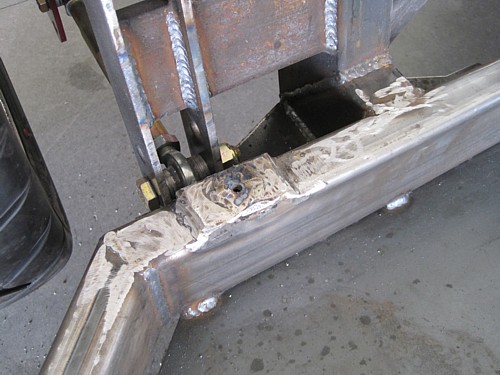
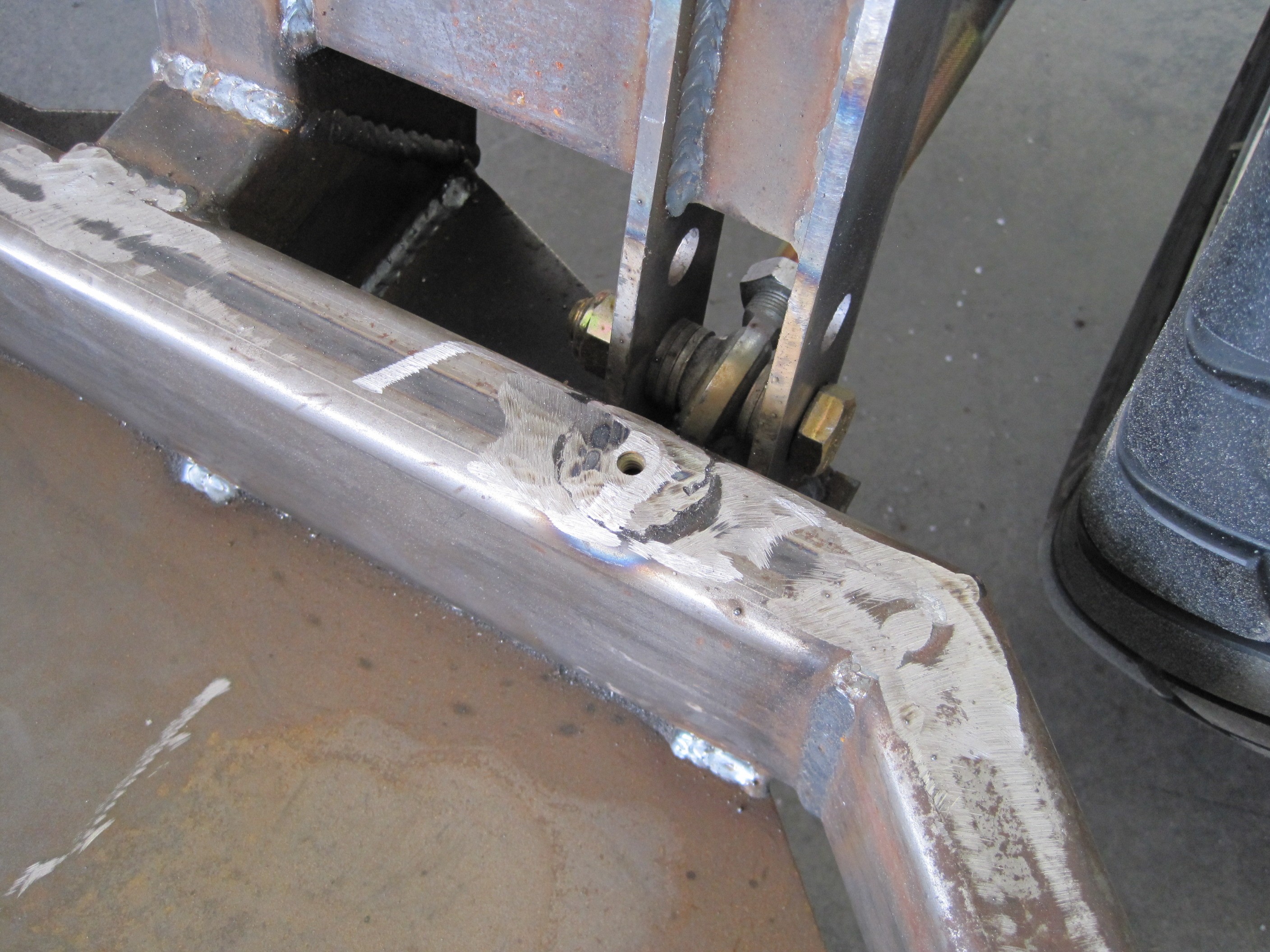
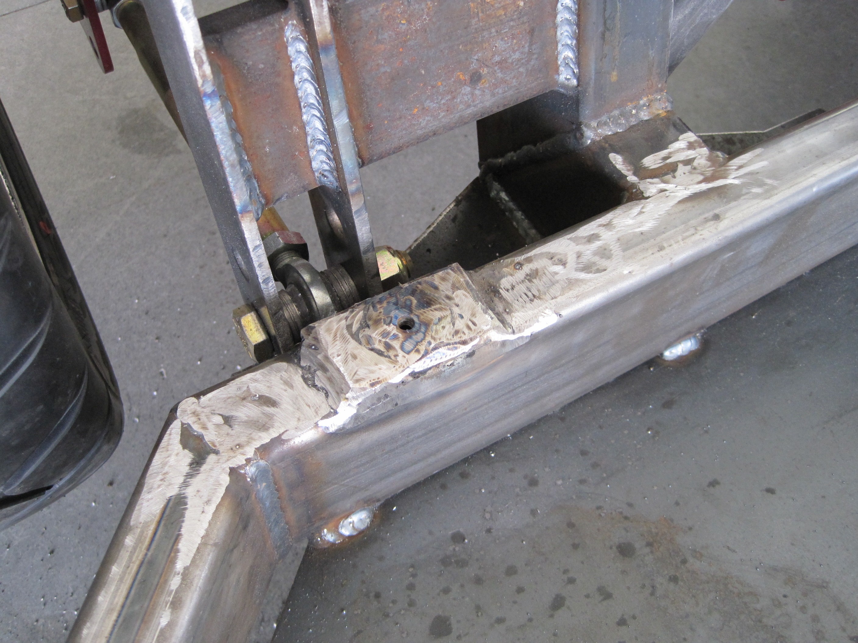
On the passenger side,
I had to mount a spacer to account for the final body position. I
welded and ground it down smooth. I leveled the rear of the body using
the distance from the frame to the floor and the frame to the wheel wells as
reference points. You have to do it this way when all the shocks are
adjustable because you need common reference points. Now when the
shocks are adjusted to equalize the spacing in the wheel wells, the body
will be level with the ground.
The next step is to
install the hard points for the front and rear mounts and that work begins
on the next page.
|