Drive Shaft
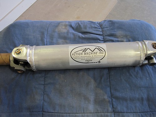
I ordered up and
received my custom drive shaft in just a couple of days. I would
recommend this company. They provide simple instructions on their web
site on how to measure for it.
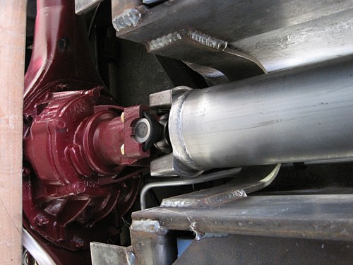
It was a simple bolt
on using standard Ford u-bolt kit.
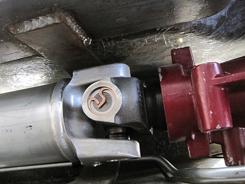
I pulled the rubber
plug out of the end and inserted the slip yoke into the transmission.
That's it.
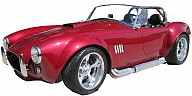
Pedals
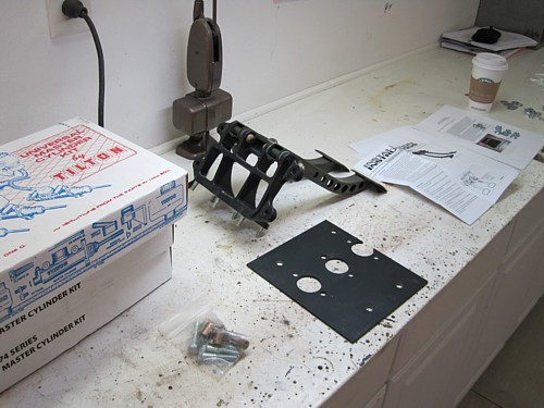
It took me a little
while to figure out the pedal assembly and then it turned out that I
installed it different than the plans call for. However, I think my
install is better because I didn't use the big honking heavy steel bracket
that came with the kit.
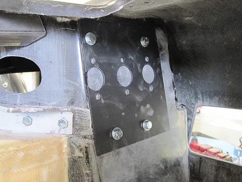
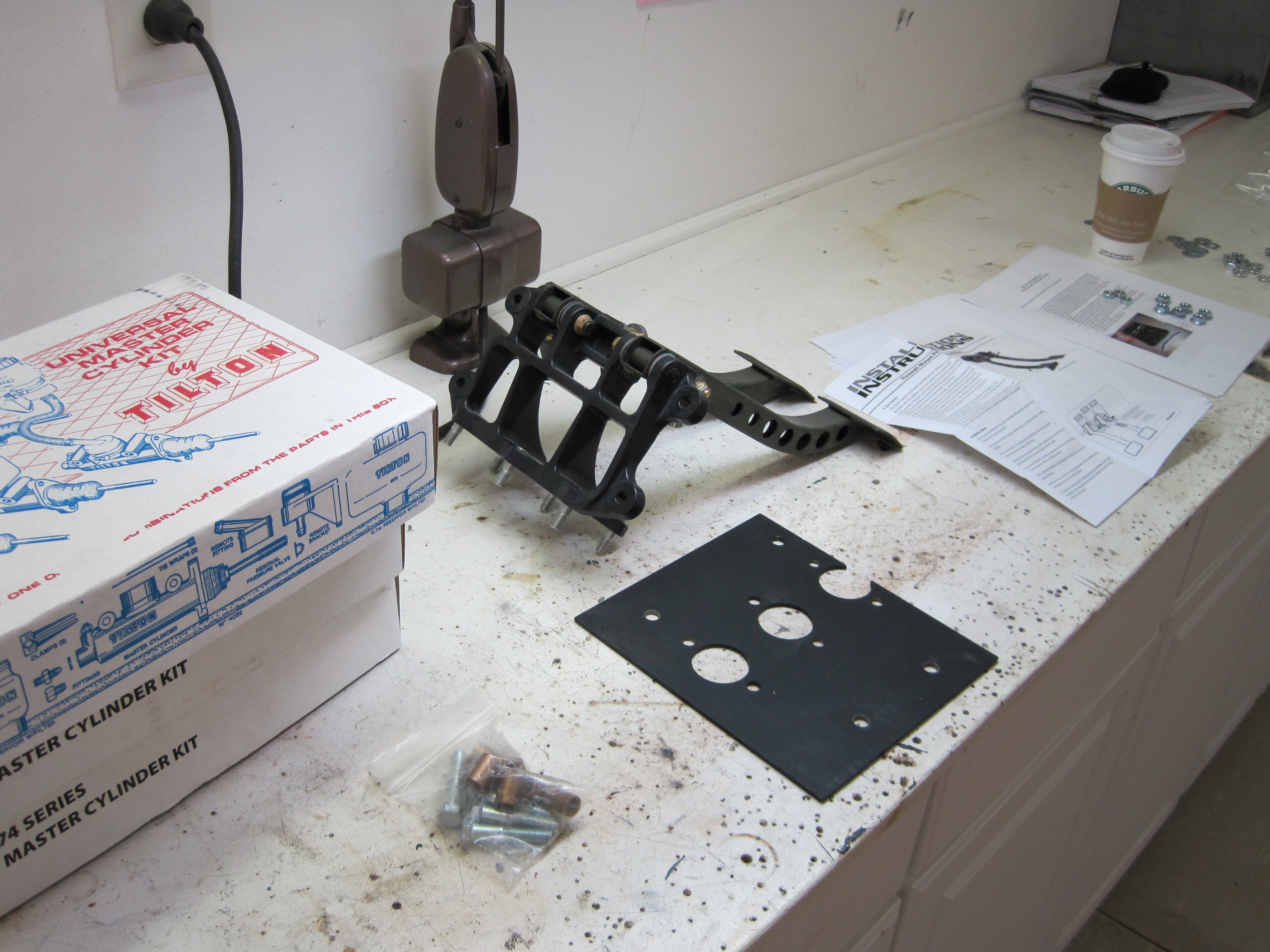
First, I located the
backing plate as high and towards the inside as I could get it.
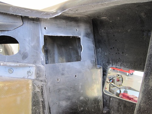
I then cut out the
firewall the dimension of the pedal assembly/
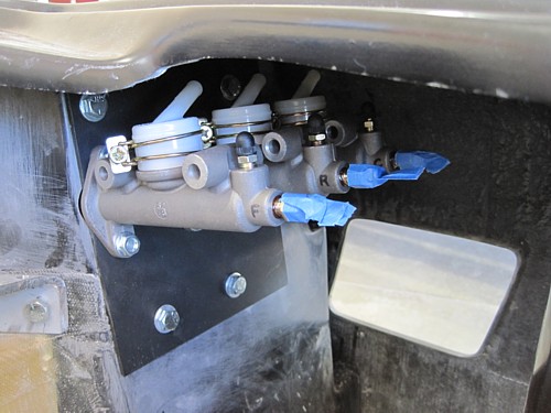
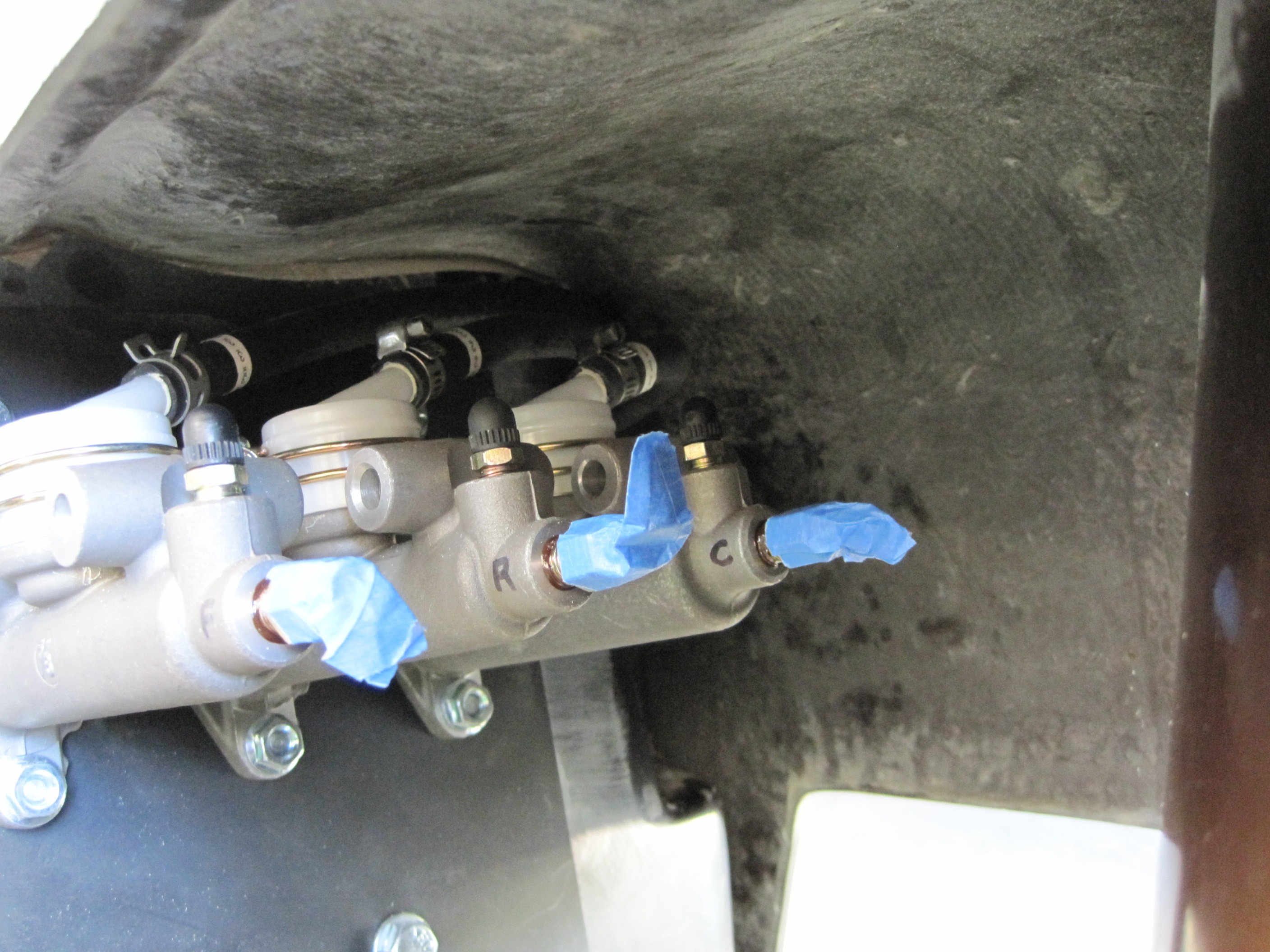
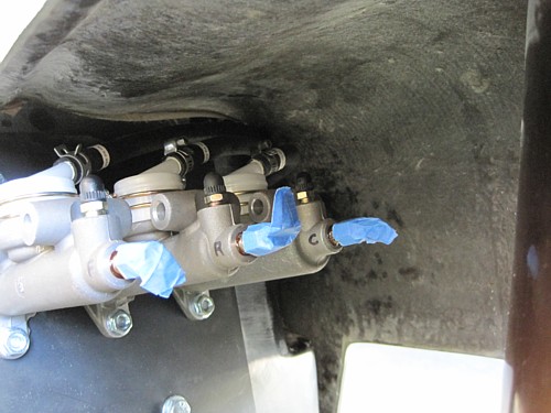
I then bolted the
pedal assembly and master cylinders directly to the plate. For
reference, the largest cylinder goes to the front brakes, the next
size goes to the rear brakes, and the smallest cylinder goes to the clutch.
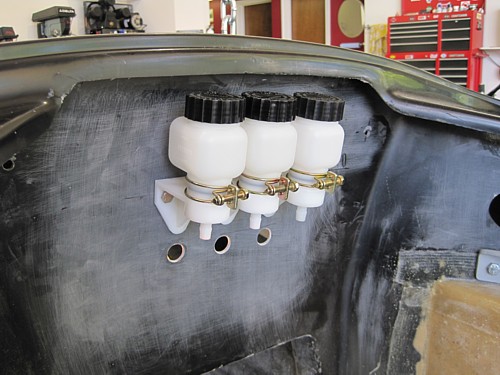
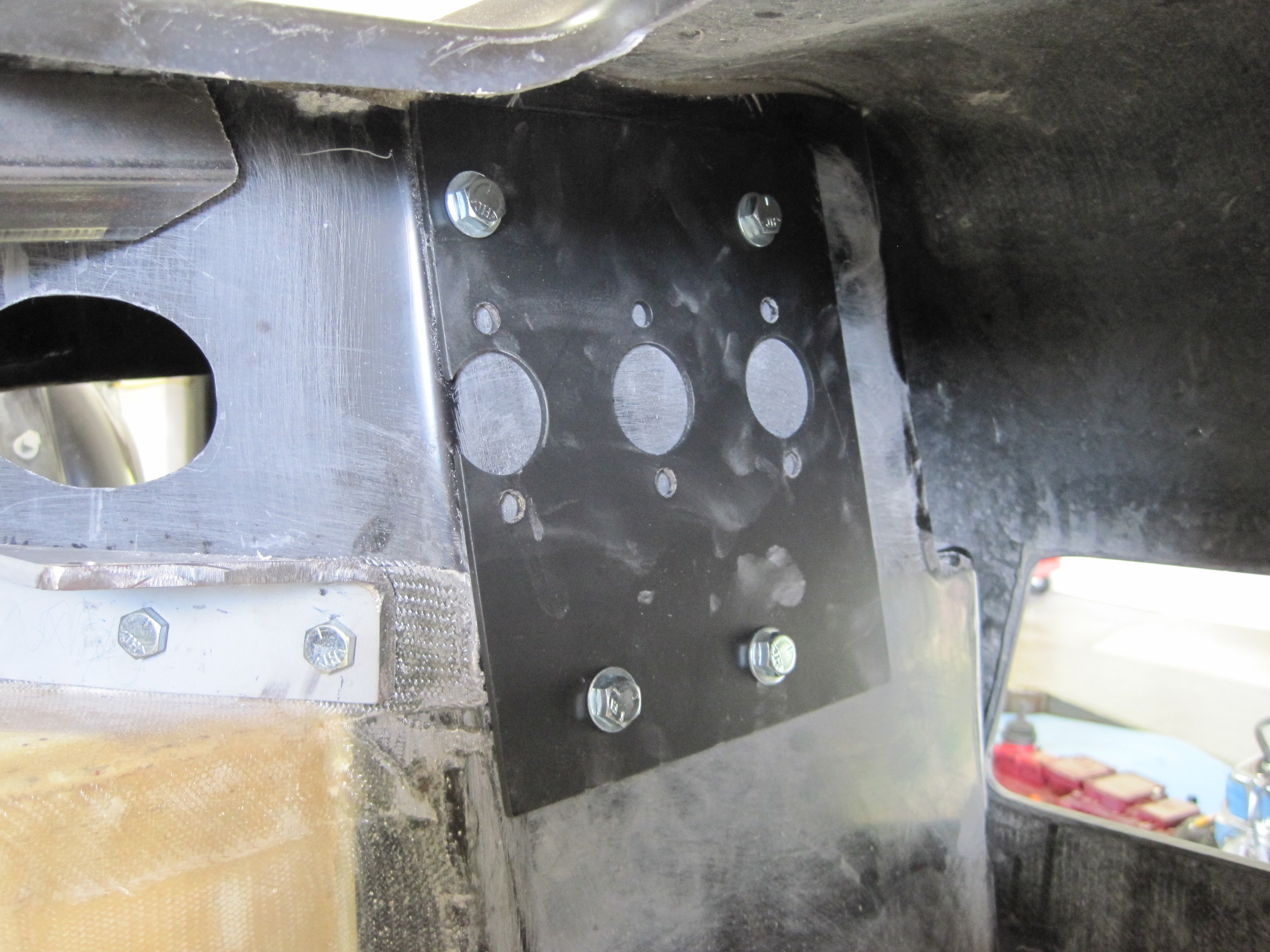
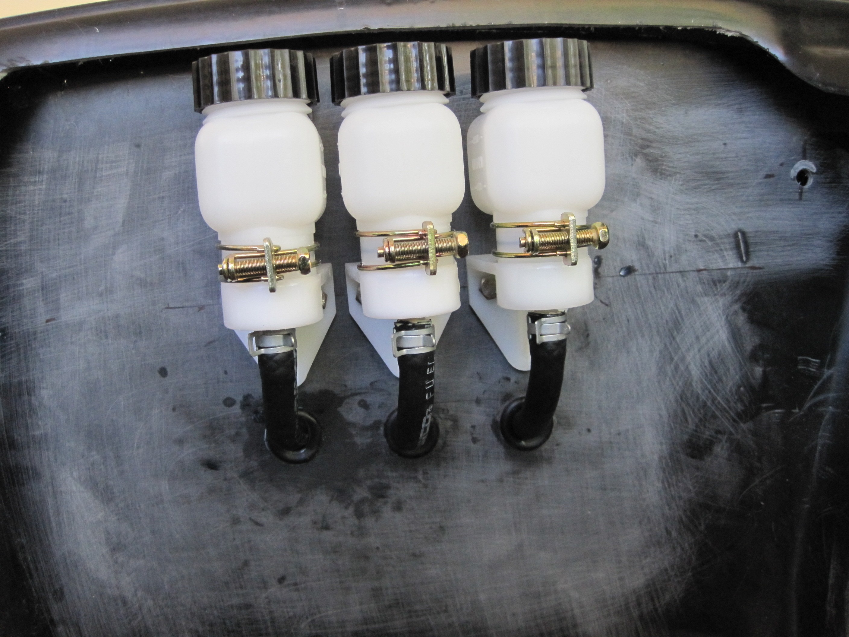
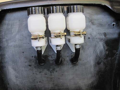
I chose to mount the
remote reservoirs in the center of the firewall. I plan to cover this
area with a stainless steel box. My electrical stuff will go just
below these. The hoses will be run inside the passenger compartment.
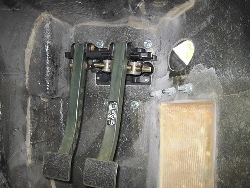
Here's the pedal
assembly bolted directly to the backing plate. I just can't see the
need for the big steel box.
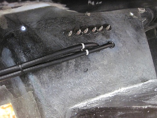
Here are the hoses
coming into the passenger compartment in the center of the firewall. I
plan to install a center console with side panels so this area cannot be
seen from the seats.
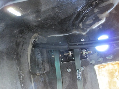
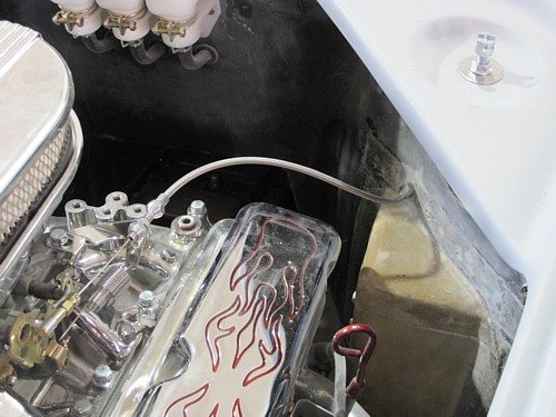
I ran the hoses above
the pedals and into the engine compartment above the vent indentation.
It's a little tight
but they fit.
The hoses run through
some rubber grommets. Next up is the gas pedal.
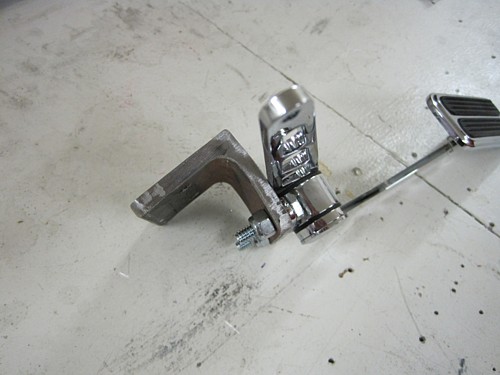
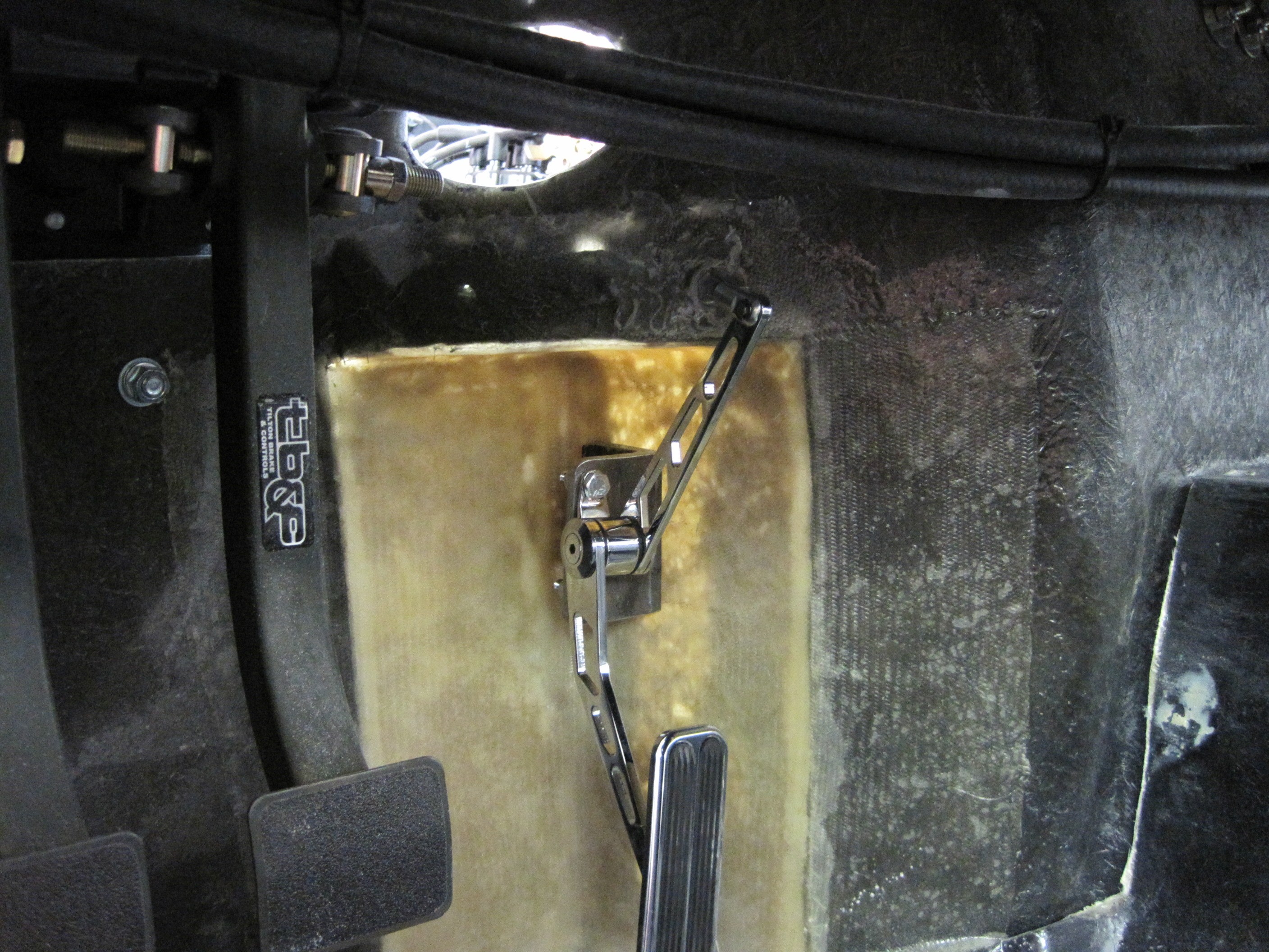
Since I built out the
foot box, the existing bracket from the kit would not work. I took a
piece of scrap angle and built a bracket. To get the pedal to hang the
way I wanted it, I had to bend the bracket inward a little and also tilt the
pedal on the face of the bracket.

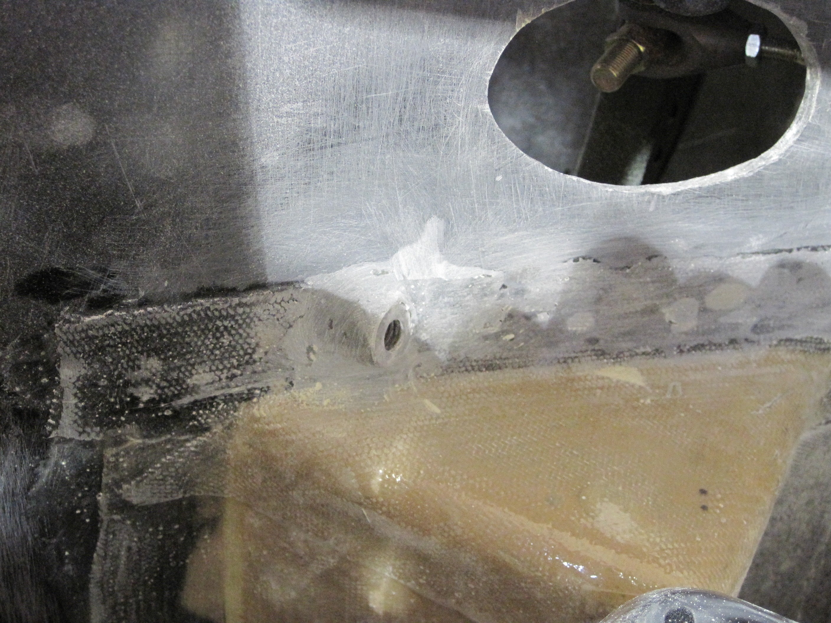
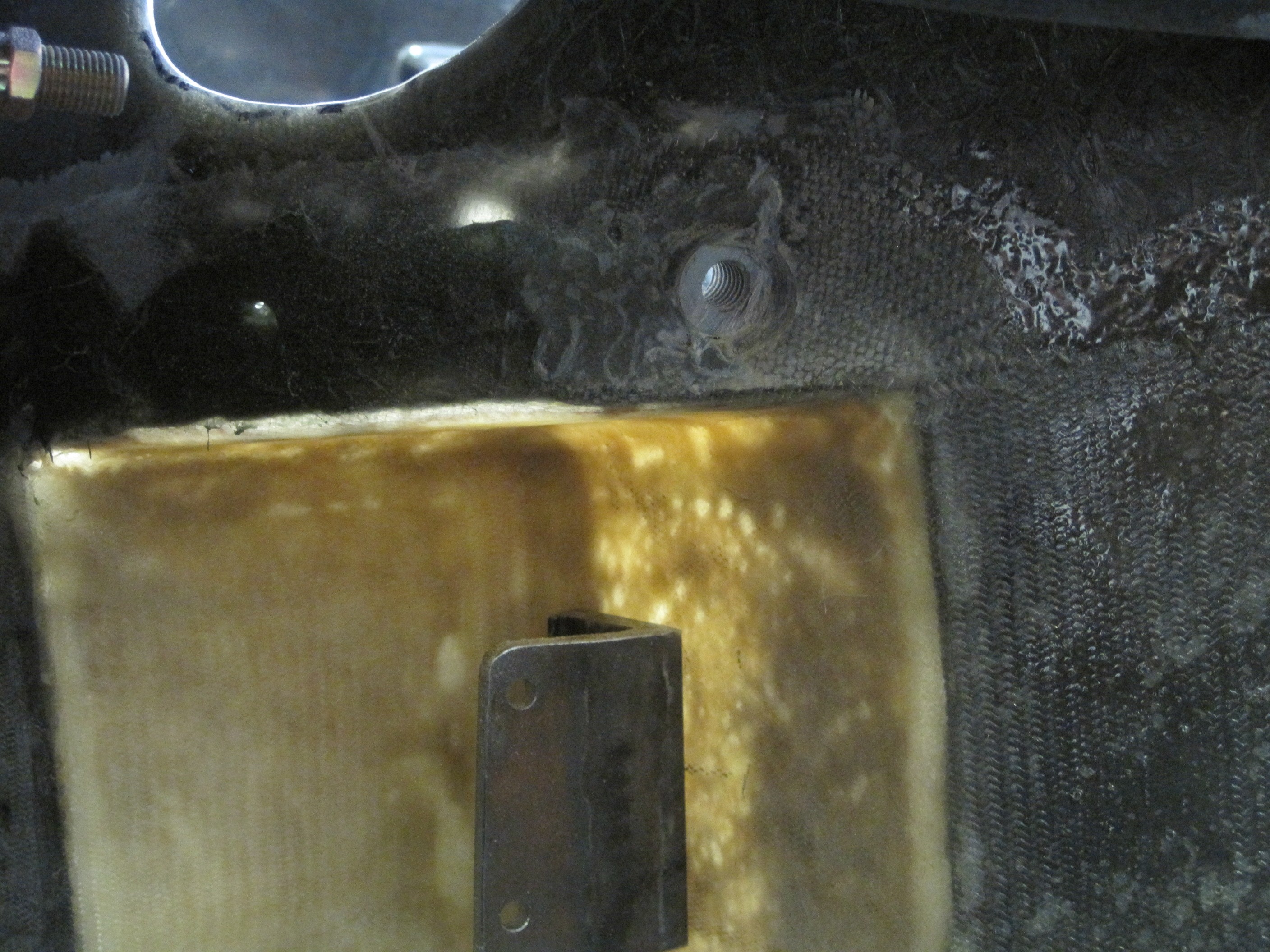
Getting the cable to
the pedal was a little tricky. To provide a hard mounting surface for
the cable end, and to accommodate the angle of the firewall, I used a scrap
piece of pipe and mounted it through the firewall. I used to glass
strands to secure it.

Here's what it looks
like on the inside.
I trimmed the cable
and mounted it per the instructions provided in the cable kit.

It's hard to see, but
it is mounted to the tip of the pedal assembly using a turnbuckle.
Next up, I move to the
engine compartment to finish up a few remaining tasks. Those pictures
begin on the next page.
|